|
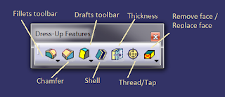
| Dressup features toolbar |
Dress up features toolbar, as the name suggests, has set of tools that are used for applying cosmetic features such as fillet, chamfer, draft etc. While tools like corner or fillet are available in sketcher too, it's advisable not to use them and instead apply such features in the part design workbench. It make the sketch simpler and modification easier. These features are generally applied towards the end, keeping in mind the standards that are being followed.
Also, as discussed previously, depending on the kind of part you are making, you would need to order your features in way that's most suitable. For example, in case of plastic hollow parts, the shell would generally be the last dressup feature. While in case of solid parts, you would apply chamfers and fillets at the end most of the time. So, keeping this in mind we shall now discuss the fillets toolbar and all other tools one by one.
The fillets toolbar comprises of various tools for applying fillet - Edge fillet, variable radius fillet, Chordal fillet, Face-face fillet and tritangent fillet.
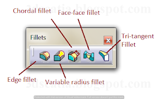 |
| Fillets toolbar |
Edge fillet - The edge fillet option can be used to apply a constant radius fillet to an edge of a part. You can select as many edges that you wish to apply a constant radius at once by selecting with mouse click. To deselect / select edges you can also use the Objects to fillet field in the fillet command. If there exists a continuity in the edges that you wish to fillet, you can select the selection mode to be 'Tangency', this will propagate and apply fillet to all edges that are tangential to the edge you selected. This is the option that's most commonly used and is preferred since it creates best finish of surfaces that are preferred for manufacturing. To make use of this, we may first apply fillet to some individual edges to make the main edge continuous and subsequently, select the main edge for applying fillet.
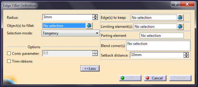 |
Edge fillet options
|
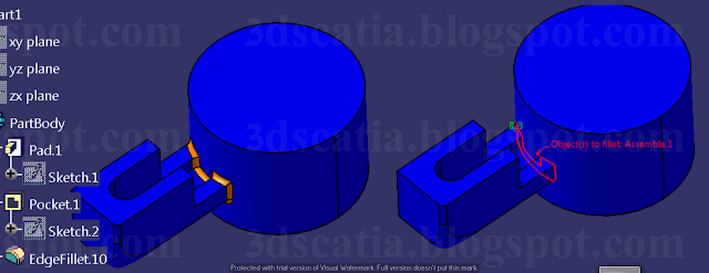
In case you wish to apply edge fillet only to the selected edge, you can choose the option 'minimal', this will blend the fillet to the other edges that are tangent to the selected edge. The intersection option can be used to automatically select the intersection edges created due to assembling of two bodies.
 |
| Selection mode - Intersection |
In case of overlapping fillets, trim ribbons option can be used to compute fillets along with tangency selection mode. The edge fillets applied to the two protrusions are shown in blue which are computed using 'trim ribbons' option. Alternatively, you can use minimal option for selection mode for which the trimmed option works implicitly.
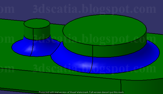 |
| Trim ribbons option used for fillet computation |
Fillets applied to edges can be limited using points, planes etc. with the use of limiting elements option. You can dynamically select the points on the edge that you wish to select as limiting elements as well as the directions in which you wish to limit the fillet. You can see in the picture, green dot surrounded by blue circle represent the limiting points and orange arrows represent the direction in which the fillet will be applied with respect to the limitation point selected.
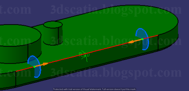 |
| Fillet - with two points chosen as limiting elements on the edge |
In case if there are edges are meeting at a vertex, setback distances for each individual edge can be set using the blend corner option. With this option, the corner can be made comparatively smoother in comparison to the edges.
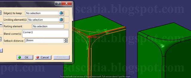 |
| Blend corner |
To select the corner, you would need to right click on the Blend corner dialogue box. To set the distance, you would need to select the individual distance value and set the distance as per requirement.
Variable radius fillet - Variable radius fillet option can be used to make a fillet of varying radius value. You can select an edge for fillet and can specify as many points on the edge as you wish. The value of radius at each of these points can be specified individually. variation of radius between points can be chosen as either linear or cubic.
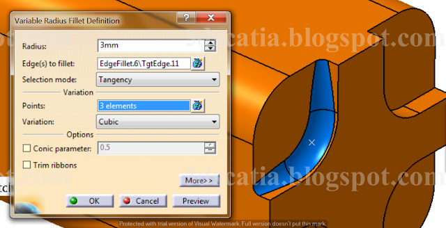 |
| Variable radius fillet (shown in blue) |
Chordal fillet - Fillet applied in case of edge fillet and variable radius fillet is specified with the radius value. In case you wish to control the fillets by specifying chord value (width) of sphere, you can use chordal fillet. In this case too, you can specify as many points and vary the chord value for fillet. Visually, you may not find much difference between the two, and most of the time, you will find yourself using the edge fillets, tritangent fillet, and variable radius fillet.
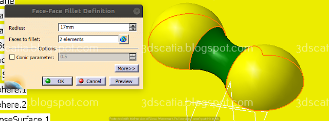 |
| Face-face fillet (in green) created between two half spheres |
Face-face fillet - Edge fillet, chordal fillet, variable radius fillet can be applied between faces which share an edge i.e. they have a common edge else they cannot be applied. So, in case two surfaces do not have a common edge, we can use face-face fillet with some limitations. You may not be able to use this option in case the faced are parallel to each other or they don't converge.
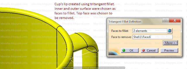 |
| Tritangent fillet dialogue box |
Tritangent fillet - The tritangent fillet too can be applied between faces that do not share a common edge. In this process the fillet that is created is tangent to the three surfaces and one of the surface is eliminated in the process. This is the type of fillet that you may use in case where you want to remove sharp edge of a cup's lip or create a rounded face. You can see below the cup's lip was created using the three surfaces, outside, inside and the top surface was chosen as the face to be removed.
We all know that chamfer is applied to edges of a part to avoid injury and to avoid stress concentration. We have the option of applying chamfer in the Sketcher workbench, which we can use to created chamfered edges. However, we should not make a sketch complex with the use of chamfer and corner available in sketcher as it makes modification difficult. We should apply fillets and chamfer in part design workbench instead.
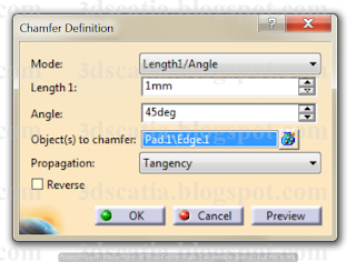 |
| Chamfer dialogue box |
What are the different ways of applying chamfer?
There are two ways that you can choose from in Catia - Length 1 and Length 2 and the other one is Length and Angle. Length 1 and Length 2 can be switched using the reverse option available in the dialogue box. Likewise the option can be used to switch Length 1 and angle
What is an ideal manner to apply chamfer / fillet or both?
If we apply chamfer or fillets in a haphazard manner, it is likely to leave sharp edges and make part design difficult. So, we should follow a certain sequence when possible. Ideally, we should identify shorter edges first and apply fillets to them, such that they allow the flow of fillets or chamfer without any obstruction. We should ideally be able to use the tangency option for propagation of chamfer or fillets for the bigger edges as it will create overall smoother edges. You can see the part below in which first the short edges were filleted and subsequently, the larger edges were applied chamfer with the use of tangency propagation. This allowed the chamfer to propagate on the larger edge easily and no sharp edges were left. If only fillets were to be applied, they should also be applied in the same manner.
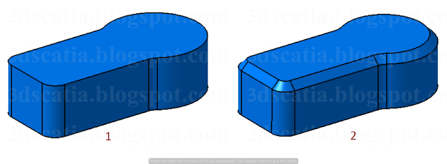 |
1. Shorter edges selected first and applied fillets. 2. Chamfer applied to the bigger edge.
|
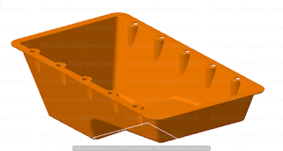 |
Oil pan made using draft as one of the
main feature, to create an interplay of surfaces. |
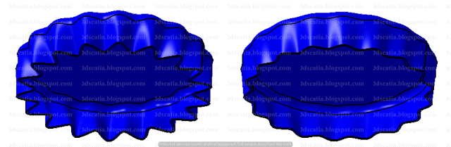
Draft is a major applied feature in most plastic parts. At times, draft may be interpreted as a design element made using some complex feature like multi-section solid or shaft etc., but it really is draft. So, therefore we should be making such features with the help of draft and not with multi section or revolve etc. Likewise if you see the oil pan made below, we may be inclined to think that we should first use multi section solid and then some other commands, however, the interplay of surfaces here is simply created with the use of draft and in the end one of the dressup feature like draft is applied.
For example the bucket below has also been made using draft applied to a solid circular extrusion and shell, because using multi section is definitely that's less than ideal when we can simply apply draft to a solid circular extrusion and then shell to get the following result.
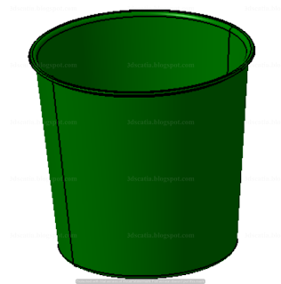 |
Bucket made with draft and shell
|
Draft is a useful dress-up feature that's used in the final stages of product design. You may have studied the process of casting which requires us to take into account certain allowances like shrinkage allowance, machining allowance etc. One of the allowance that is taken into consideration is the draft allowance. To prevent damage to the leading edges of the mould and facilitate pattern removal, draft allowance is given, which is essentially a taper applied on the vertical surfaces. The amount of taper applied is dependent on depth, material, thickness, surface finish, whether surfaces are internal / external and other such factors. The same is true for plastic parts created using injection moulding. Draft applied, enables easy removal of the moulded plastic part and it reduces the chance of damage to the part during release.
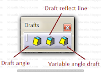 |
Drafts toolbar
|
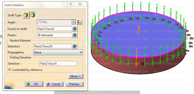
In Catia, there are three option available for applying draft and these are - Draft angle, Draft reflect line and Variable angle draft. Some things to understand before we study the draft option are - Pulling direction and Neutral element. Pulling direction is the direction in which the core of the part or the side cores of the part will be removed, so we need to specify this for the purpose of draft application. The direction chosen will be dependent on part's design. Other thing we need to know is the neutral surface / plane. It is the section that will not undergo any change due to the applied draft and it is the face with respect to which the draft angle is applied.
Draft angle - Depending on your requirements, you can select the faces to which you need to apply draft. If you need to apply it to just one face or two face etc., then you can select those faces individually and no need to select the option -
Selection by neutral face. If you wish to apply draft to all faces, you can select all faces with the help of neutral element. You can simply select the neutral element, with the option selection by neutral face selected. This will select all faces adjoining the neutral element as faces to which draft needs to be applied. The pulling direction is shown in orange and you can select it with the help of neutral surface or any other direction (depending on your choice).
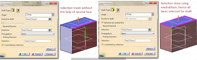 |
| Faces to be drafted (individual selection vs selection made using neutral face) |
The neutral element may not necessarily be a 2D plane or surface as shown above and you may even choose multiple faces as neutral elements, in case if it is a surface that is continuous in tangency, as shown below, you can select the propagation option as smooth to select all of it as neutral element. The draft applied will vary depending upon the neutral surface selected.
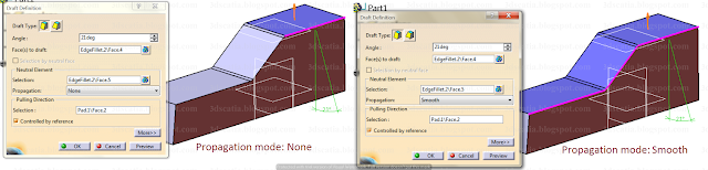 |
| Neutral element selection can be either none or smooth, the draft will be applied accordingly |
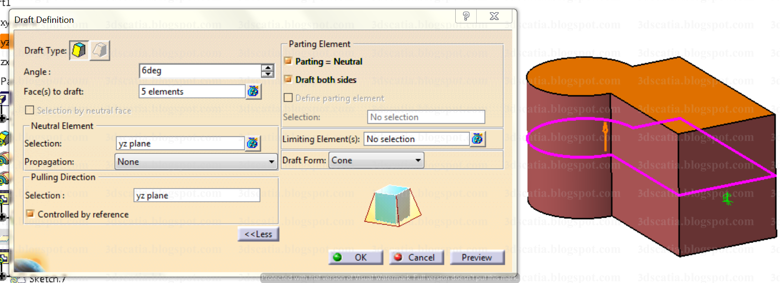
In the above case, we have applied draft only on one side. But what if the parting line is such that we need to apply draft on both sides. For example, for a part that's shown below.
 |
| Part that uses 'draft both sides' as option |
As you can see that in the outer part, the draft has been applied using centre as parting element. So, to apply such a draft, we can use options that are available in the more section of the draft toolbar. Where we can use the option draft both sides, after selection parting = neutral.
 |
| Draft applied to both sides of the outer surfaces using Parting = Neutral and Draft both sides |
In case if you wish to apply draft to just one side of the part, you can indeed select Define parting element, this will apply drafts to the selected side only up till the parting element. For this, you would need to deselect both the options selected above and define the parting element. You can limit the draft application by selecting plane as limiting element and create drafts as shown below.
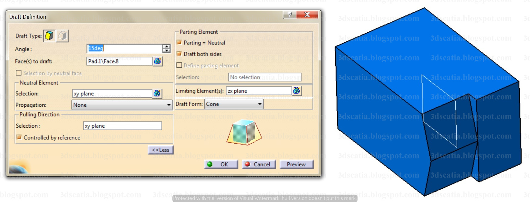 |
| Draft created using shown plane as limiting element |
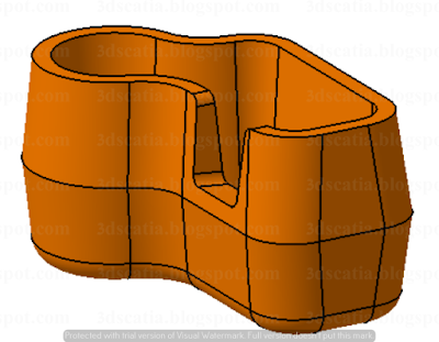
Variable angle draft - In case of variable angle draft, you can select points on the neutral elements. On each of these points you can specify the angle of draft as per your choice. So, the draft applied on surfaces is not same across the neutral element but varied depending upon the number of points you select and the angle you specify on these points. If done properly, you would be able to make complex object as shown below with the help of this.
 |
Object created using Variable angle draft, shell and fillet. To make modification easier formula was also used.
|
 |
| Variable angle draft applied to circular cap using 36 points in total, and driven using parameters |
You can select the points on the edges as you want and modify the angles individually as per preference.
Draft reflect line - The options that we used previously i.e.
variable angle draft as well as
draft angle can be used to apply draft on faces that are planar in the direction in which the draft is applied. However if we need to apply draft on filleted surfaces or round surfaces like sphere or the cylindrical surface longitudinally as shown, we can use the draft reflect line option to apply draft on the selected faces with the use of reflect lines. Options like parting element, limiting elements and pulling direction can be used as in the previous draft options.
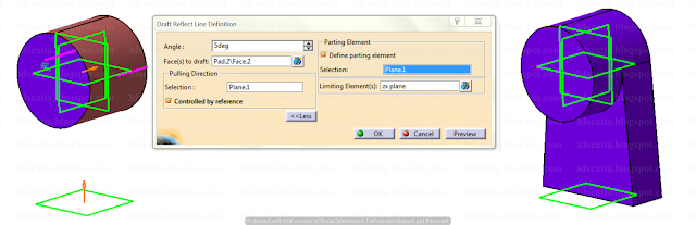 |
| Draft applied using draft reflect line on cylinder. |
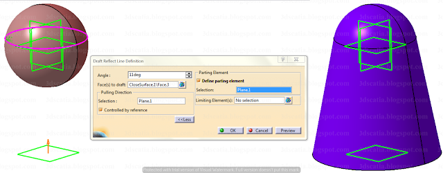 |
Draft reflect line can also be used to apply draft on spherical surfaces
|
The shell command can be used to make hollow parts of regular or irregular thicknesses. For example hollow plastic parts made using the process of injection moulding or parts made using blow moulding process can be modelled using shell command. Shell command may also be used to model parts made using sheet-metal too. The great benefit that shell commands offers is that we need to model solid part as per our desire and the internal / external surfaces can be derived using the command and thickness can be added as per preference. In the drafts toolbar we saw how draft may be applied to the solid part to model oil pan. After the draft is applied, shell command may be used to make it hollow and remove one of the surfaces as shown below.
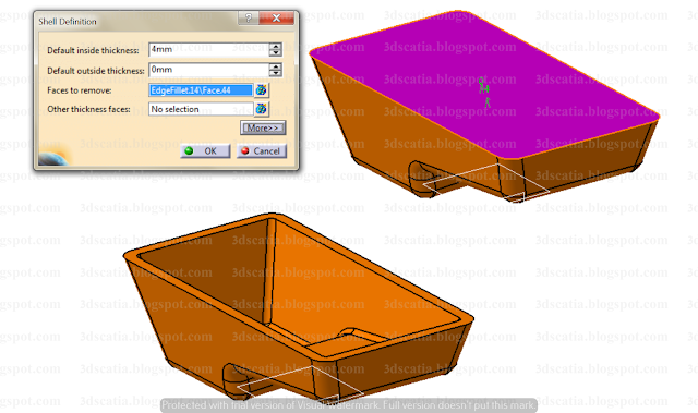 |
| Shell applied to solid to transform it into hollow body of regular thickness |
Shell has been applied to the solid part. The face that's being removed is shown in pink. The thickness is added to the inner side (4mm). The outer surface has been kept as same since no outer thickness has been applied. In case if we sih to apply irregular thicknesses to different surfaces, we can select other thickness faces and apply a thickness value other than default thickness value.
Thickness - Parts designed in Catia will have a specification tree i.e. you will be able to see the history of the features applied using tools. You would also be able to see the sketches made etc. So, you can always modify them by editing those features. However, in case where conditions are less than ideal i.e. feature modification is difficult or in situations where part history is not available i.e parts exported to Catia from other softwares using STEP files or IGES solids, we can use local modification commands. This is the tool that you can use where reworking may be time consuming or extremely difficult. Thickness is one such tool that can be used for local modification of such part surfaces which are troubling modification.
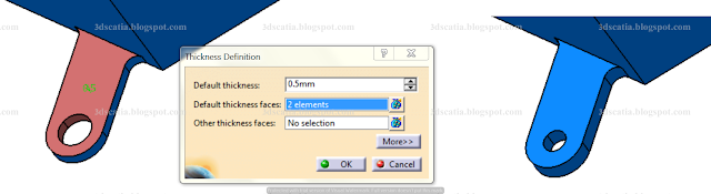 |
Selected surfaces showed in colour (other than blue), on the right you can see the result.
A larger value will remove the hole. |
For example, the bracket hole for mounting was causing trouble and was failing. However, the sketch could not be modified since the part has no history as it was imported as STEP file from other software. So, it was decided to add thickness to the face and rework the hole dia. So, both the hole as well as one of the surface were selected for adding thickness, and the thickness was added and hole was removed. Subsequently, a hole of smaller dia may be applied to prevent failure. If desired, another surface for adding a thickness can also be selected if desired, and it may have a thickness value other than the default thickness provided.
Thread / Tap - When we use the hole command, present in the sketch based features toolbar, we have an option to apply the threads within that command. As mentioned previously, this is cosmetic in nature and is shown only in the specification tree and will be recognised during CNC tool path generation. However, what if the hole is created using a pocket command using a circle as a sketch. Or if a thread is required on an external surface. In such cases the Thread/Tap tool can be used. Like in the Hole command, we have the similar option of either using the standards as defined by default or we can apply threads as per our preference. In the numerical definition section, we can choose a metric thick or metric thin pitch or simply apply threads without these standards. Below we can choose if it has to be right threaded or left threaded.
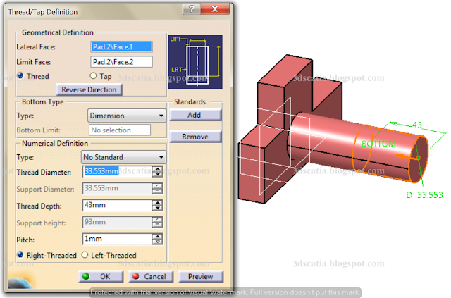 |
| Thread/Tap tool - Used to apply thread on an external feature. |
Whether the thread is internal or external can be chosen from Geometrical definition section, i.e. you can choose whether it's a thread or a tap. And from the same section you can choose the direction of thread in which it is applied. Thread depth can be specified from the bottom type section, where you can limit it with the use of plane or dimension value, or apply it for entire support.
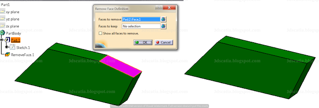
Remove face - The name of the tool is self-explanatory. The command can be used to remove a face entirely. We can then apply new features or modify the existing feature as per our needs. The feature is more likely to be used where modification of the existing features is not possible i.e. cases where a part has been imported from other software in the form of STEP file IGES file etc. Or it may be used in case where it requires tremendous amount of rework, which may be more time-consuming and counter productive.
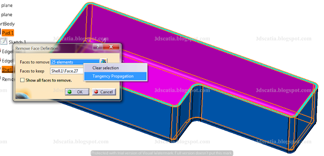 |
| Remove face applied to remove shell |
Besides the option, where you can choose the faces to remove, you also have an option to specify the faces which you wish to keep. This will ensure that those faces will not be removed. To select the faces easily, you can use the contextual option of 'tangency propagation' by using right click. The faces to be removed are shown in pink. This will remove the shell and make the box a solid body. It is to be kept in mind that remove face cannot generate a new face and would therefore not be applicable where a face does not exist to reconstruct a feature with. For example, in the case above, The face shown in turquoise colour is crucial for replace face. Without it, the replace face would not have worked. For example in the case below, the faces that can be built lie between faces that can extend and are not parallel.
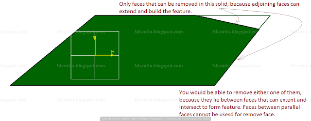 |
| Front view of solid body with different surface in the view |
When we apply the remove face to the top face, the adjoining faces extend to build the solid. The result can be seen below.
 |
Remove face applied to one of the surface.
|
Replace face - The
Replace face command can be used to replace an existing face of solid with another face. The new face may be of a surface (as shown below). The command will not only replace the face with the selected face but also extend or trim the face.
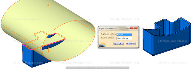 |
The top face of shell (shown in pink) replaced with face conforming to that of yellow surface
(We will learn, how to create surfaces ahead in the blog) |
The yellow surface was make by extruding an ellipse in wireframe and surface design workbench. The replacing surface is yellow, while face to remove is in pink color.


