 |
| Knowledge toolbar |
You would be aware that in engineering design, we use knowledge of various principles. For example, in case of a beam, the section width may have certain relation with height, or thickness. We also know many other geometric relations like an equilateral triangle has equal sides, rectangle's opposite sides are equal etc. Catia can effectively integrate into the design itself using formula.
Catia can also deal effectively with fog i.e. functions i.e. f(x). You can see some of the sample functions that Catia can work with using this link. Before we can work with functions or formula, there's a more fundamental thing you should know about - parameters, since it lays foundation for defining functions as well as formula and makes them more meaningful and understandable. Let us now, how we can define parameters, relations and use them.
Parameter
A parameter is the most fundamental piece of information that you can build into your design. For example, in case if you wish to design a beam section, the height, width and thickness of the beam will be the parameters that you use to create the geometry. The parameters above are of the type length i.e. they have units mm or any other unit that's typical of length. You may also have other parameters like angle, which may have units of degree etc. Catia has all the parameters present that you can define using a name of your choice. Below you can see some of these parameters.
 |
| Parameters you can define in Catia |
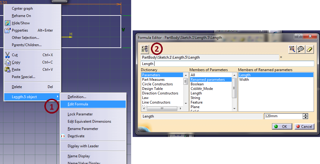
To define a parameter, you would need to use Formula tool. Subsequently, use the following steps.
- Select parameter type using dropdown.
- Click on 'New parameter of type' (This will create a new parameter).
- Give a name that you prefer.
- Give a parameter value you prefer.
- After you click apply or OK the parameter will be created.
 |
| New length parameter with the name 'width' created using formula tool |
A thing to keep in mind is that parameter / relation will not be displayed by default in the specification tree. You can turn it ON from Tools>Options>Infrastructure>Part Infrastructure>Display. From the tab, you can select the radio buttons Parameters and Relations. The value of parameters will not be displayed by default, you can turn this ON from Tool>Option>General>Parameters and Measure>Knowledge. From the tab, select the radio buttons With value and With formula. After this, you should be able to see the parameter values and formula. Likewise if we apply a formula, that will also be shown.
 |
| Specification tree with parameter and value |
Formula
A formula is basically a relationship that exists between different parameters. So, before you apply a formula, you should add all parameters that may be present in your formula. For example, above we added width as parameter, we may add other parameters too like Length, thickness, etc. subsequently, we may add a formula defining the relationship between the parameters. Consider this that in an analysis file, you wish to modify the applicable force according to the relationship F=m.a. So, you would first need to define the parameters, m i.e. mass value, and other is the acceleration value, you would also need to define the parameter force as a parameter before the formula is define for its calculation. Instead of defining a value, we instead define the formula by using the add formula button. The value of the force parameter will be calculated depending upon the formula that you define. This makes our task easier parameter values of mass and acceleration can be changed at any time, the force will be automatically computed according to these parameter values. You can define as complex or basic relationships and drive your design based on this knowledge.
 |
| Specification tree showing added formula |
Design table
A design table is best utilized to swiftly create a family of parts. For example. I beam of different cross section, bolts of different size etc. A design table can utilize different parameters within an MS Excel file for documentation as well as drive geometry of the parts. To effectively use design table, it's important that you first create all parameters as done above. Subsequently dimension the sketch and drive the dimensions of the sketch and parts using these parameters. To do this, you would need to right click on the dimension of the sketch or any dimension that needs to be associated with the parameter, subsequently, it needs to be associated with the appropriate renamed parameter.
 |
| Associating dimension with a parameter |
To create a design table, you would need to put all parameters that you have created into an excel file to easily apply a configuration of preference. For example, consider the I section sketch that we created below and associated with the parameters.
 |
| A sketch created with dimensions associated with parameters |
The specification tree showing all parameters that the above sketch has used can be seen below.
 |
| Parameters associated with I section |
After doing all this the next step would be to click on Design Table option in the toolbar. Subsequently, you can name the excel file as you want. You would need to select the option Create a design table with current parameter values.
 |
| Create design table |
You would need to select the filter type Renamed parameters and add all parameters to Inserted parameters section, this will add these parameters to design table.
 |
| Parameters added to Inserted parameters section |
After you press OK, a dialog box will appear and will allow you to save the excel file in a location of your choice. After you save the file, the dialog box will appear as below.
 |
| Design table - Configurations available |
You can use this dialogue box to Edit table and add as many configuration rows as possible. The above dialog box can be opened at anytime using the specification tree Relations section The values you enter in the excel file will appear in the dialog box.
 |
| Configuration number two applied using double click |
You can also as apply a configuration of your choice from the dialogue box shown above simply by double clicking on the configuration of your preference. The concept of design table can be extended and applied as widely as possible to drive designs easily and swiftly. For example, you may group holes of a particular kind with a single parameter, or draft angles with a single parameter etc.
Law
Law tool in Catia is illustrated as fog which is basically mathematical notation for functions. If f(x) and g(x) are two different functions fog = f(g(x)), so fog is known as f of g(x) where f is an outer function and g is an inner function. How to use Law practically will be beyond the scope of this tutorial which intends to equip you will basic skill in Catia. Nonetheless, one great example that depicts the use of Law can be found here, with the use of this tutorial, you should be able to create an involute profile of a spur gear.