 |
| Properties of elements, bodies, planes can be accessed using right click |
A distinction needs to be made that you can not only modify the properties of the entire Part body, but also a particular face of certain solid or a surface etc. This access to the properties of the element are available with the right-click of the mouse i.e. you can right-click on the particular element whose properties you wish to change and subsequently apply the properties.
 |
| Available tabs within properties option - Mechanical, Feature and Graphic properties |
A thing to keep in mind while modifying properties is that, not all options will be available for modification and some are not highlighted simply because they are slave to other options that need to be exercised first. Nonetheless, the intent of this post is to make you aware that there are other ways to modify the graphic properties.
Apply material
 |
| Apply material |
Applying a material to a solid model is of significance if you wish to perform analysis on part model and check it for strength, or how it will appear visually etc. The library of materials is presented when the tool is selected.
 |
| Material library |
When a material is applied, mechanical properties like modulus of elasticity, Poisson ratio, Density and Thermal expansion and Yield strength are set for the solid model. In addition, the rendering properties and other details are also set. You can view these properties for the respective material by double clicking on the material of your choice.
 |
| Material properties |
To apply a material, you would need to select the Body or Part body to which you wish to apply the material. After you select the body, the apply material option will be highlighted. Modification of the properties is not possible from the above dialogue box. However, after you have applied the material, you can set the properties by double clicking the material in the specification tree, or using the Right-click> Properties option.
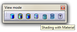 |
| View mode to be changed to 'Shading with material' |
The material cannot be visualised directly. To see if the material has been applied, you would need to change the view mode to Shading with material from the View toolbar.
Graphic properties toolbar
 |
| Graphic properties toolbar |
 |
| Part body modified using Graphic properties toolbar |
The concept of layers is similar to the ones that is used in other softwares like Autocad etc. It acts as an umbrella under which you can group different graphic properties that we discussed like transparency, line type, style etc. So, with the use of layers application of graphic properties becomes even more easy. The layers can be used to group part bodies or different element if the need arises.
Similarly, you can use point symbol for points created using reference elements toolbar and other tools. Painter can be used to copy properties from one set of elements to another. To use painter, you would first need to select the command. Subsequently, you would need to first select the elements that you wish to be painted and then the elements from which you wish to copy the properties from.
The wizard can be used for detailed investigation of graphic properties of the part bodies, and geometry that you create. It's beyond the scope of this lesson and is indeed not very useful if you are just starting to learn Catia. We may discuss this in advanced topic and see how this can be used for the purpose that it may serve and can be used for troubleshooting.