 |
| Wireframe toolbar |
We have already seen the tools like Point, Line and Plane. These are the same options that we used in Part-design for creating reference elements, and can be used in the same way as we used them previously. We will now look at the new tools that are particular to the Wireframe and Surface design workbench.
Projection
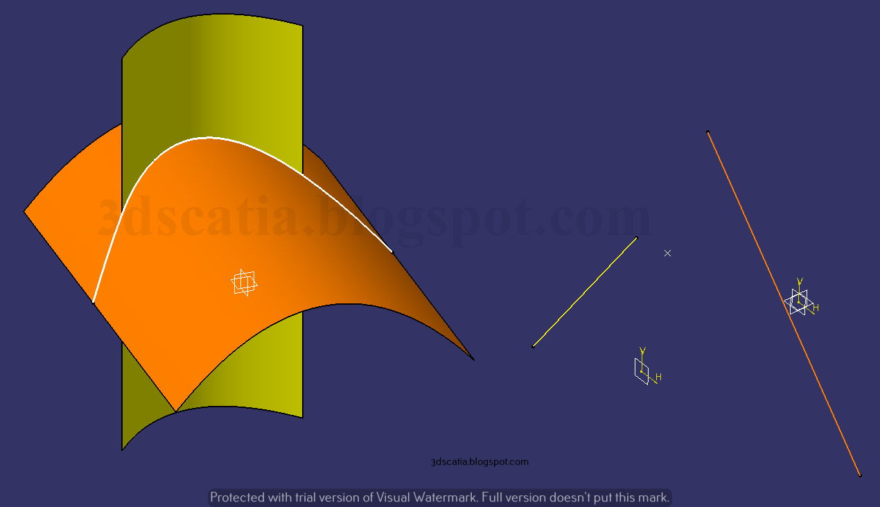
Projection tool can be used to project wireframe i.e points or lines onto a surface or a plane. So you can imagine what the output would be like when you project a point or line onto a surface / plane. You can either use the Normal method or if needed you can apply projection about a particular direction. Here we have projected a planar curve i.e. Circle.1 onto a Multi-sections Surface.1.
 |
| Blue circle projected onto Yellow surface using Z direction, the result is in Red. |
Here, we used the Nearest Solution option to keep the upper curve which was nearer to the original curve. If the option is not used, you will get two results and also won't be able to check / apply smoothing. In case of multiple results option, you would also get 'Multi-result management' dialogue box that you can use to keep the option you prefer.
 |
| In case of more than one result, Multi-result Management dialogue box shown (Without the use of nearest solution option) |
A thing to keep in mind is that projection of non-planar curves onto non-planar surfaces or projection of even planar curves onto non-planar surfaces can yield result which are quite unexpected, and in such cases, it's best to project along the desired direction, like we have done in this case (along z direction). Smoothing can be applied / checked and deviation value can be prescribed.
Intersection
Intersection computation can be done between various elements such as line-line, line-surface, surface-surface, surface-solid etc. The result can be varying and can be tuned. For example, two coplanar lines can yield curve as well as points. You can select from the dialogue box as shown below.
 |
| Intersection of two coplanar and overlapping lines can yield curve or points |
If the lines are not intersecting, you can use the option to 'Extend linear support for intersection'. This will compute the intersection considering the lines would intersect.
 |
| Intersection computation with extension option used for both lines |
Intersection computation between surface-part can yield contour or surface based on selection, and the results for both are shown below.
 |
| Intersection between surface-part |
 |
| Left: Use of extrapolation on first element. Right: Intersection of two non-coplanar lines |
Points and Planes repetition
 |
| Point and Planes created by selecting the curve |
There option Instances and spacing will be available if you choose the first point. In this case you also have the option to choose the direction with respect to the reference first point. The Instances option automatically divides the distances between the points and you can specify the total number of instances. While in case of Instances and spacing, you can specify the spacing between the points and point creation happens independent of the curve length. In this case, the repetition mode (absolute or relative) can be chosen, this is same as we studied when creating points. If you use the option Create in new body, points will be added in a geometrical set. A thing to keep in mind is that all points created are independent and if you double click on the points and planes created, you will not get the Points and Planes dialogue box. So in essence the command is not editable after you proceed ahead in the design.
Axis
The tool can be used to create axis of a circle, ellipse, arc etc. Depending upon whether you choose to create axis of an ellipse or circle, you will be provided with options pertaining to the selection. Axis in case of circle may be normal to the circle and passing through the center, or it may aligned to any direction you specify or perpendicular to that direction/plane.
 |
| Major axis of the Ellipse created using the tool |
While in case of ellipse, you get the option to create a minor axis, major axis or an axis normal to ellipse. Above you can see an axis created using this tool.
Polyline
A polyline tool is the easiest way to make a 3D line with the use of multiple points. Not only can you make the polyline, simultaneously, you can apply radius value at corners while you make them.
 |
| Five points used to create polyline and radius value of 5mm applied at point 3 |
The line above was made using the pre-existing points and a radius value was applied at point 3. If need be, you can apply radius at end points too by using the 'Close polyline' option.
Planes between
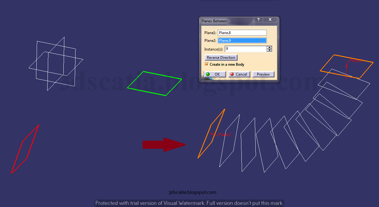
The tool can be used to create multiple planes with the use of two planes. You can specify the number of planes you want. Below you can see two already existing planes in red and green colour.
 |
| Planes between option used to create multiple planes between Green and Red plane |
The planes in white are made suing the planes between command. You can change the direction if you wish to have planes on the other side of these planes, it's possible because these planes are not parallel.
Circle
To make a circle, or an arc, you need not make a sketch. Instead you can make a circle using the Circle tool. It lets you define a point as centre and radius value etc. to define a circle. There are several options to choose from, if you are wish to use existing geometry for circle creation.
 |
| Arc made using the option Two points and Radius |
Options like two points and radius, tritangent, bitangent and radius etc. are such examples. Making it would be really straight forward and is much like remembering elementary geometry.
Corner
Corner is best utilized by creating multiple radiuses at once in a line with multiple vertex. To do this, you can select the line and use the option "corner on vertex". Below you can see that we selected the square profile and radiuses were applied at once using the corner on vertex option.
 |
| Corner applied to a square profile using the option 'Corner on vertex' |
You can also use the option to apply corners to separate lines. To apply corner to the coplanar and intersecting lines, you can use the option, corner on support. However, if the lines are not coplanar, you can use the 3D corner option.
Connect Curve
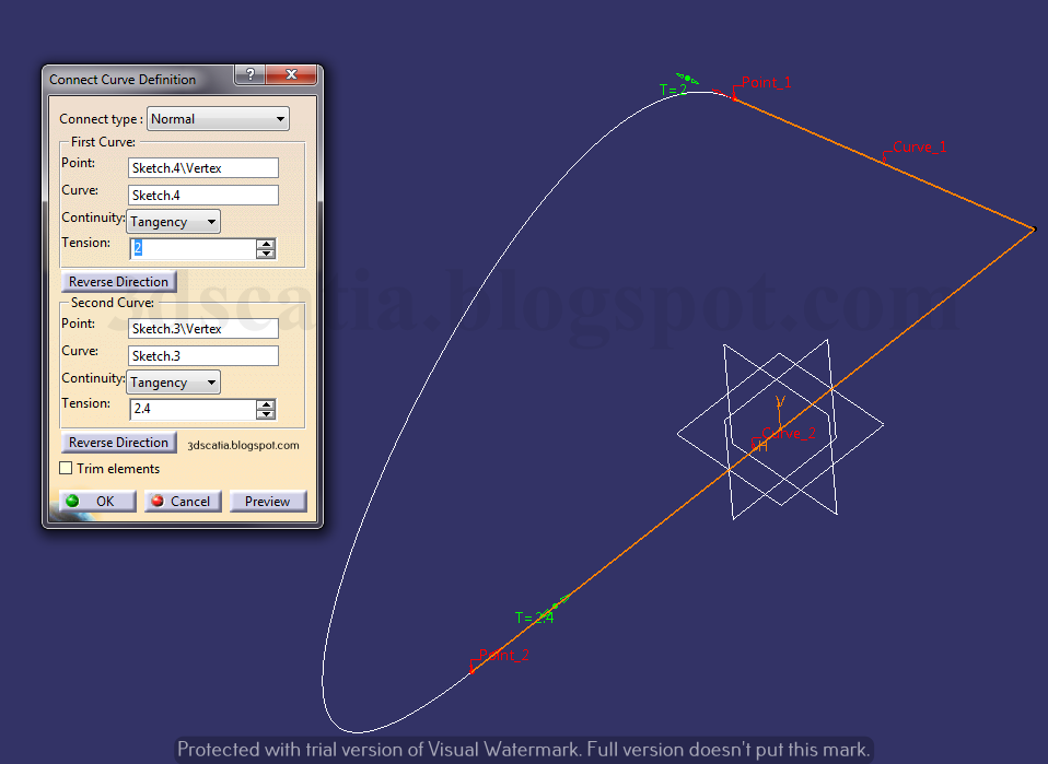
To connect two line or curves etc. you can use the connect curve option. You would need to explicitly select the points of the two curves which you wish to connect at. The associated curves with the points you select will be selected automatically.
 |
| Connect curve |
You get the option to specify the direction of connection, continuity type and tension at each point. If required to make many curves of similar type, you can change the option from Normal to Base Curve, this will allow you to select a curve for reference and the curve that's made will have the similar orientation.
Spline
You can make a spline in Wireframe and Surface design workbench of Catia, in much the same way as you did in Sketcher workbench. However, unlike the Sketcher, you cannot simply create points by clicking. So, you would require to make points first, Subsequently, you can create a spline in much the same way.
 |
| Spline made using multiple points and tangent directions defined at some points |
There are options to add points in between, after, before etc. Also. you can add tensions at the points using lines or axes as tangents directions, and close the spline using 'Close Spline' option. If points are on a plane or surface, you can exercise the 'Geometry on Support' option.
Helix
Helis can prove to be quite useful for modeling complex and bespoke springs. To define a helix, you would require an axis, a starting point. In addition, you would need to define the pitch and total height of the spring.
 |
| Helix made using profile |
In Catia, you can also define a custom profile (as we have done in this case) to drive the helix curve. The profile's starting point most coincide with the helix starting point, otherwise, you would not be able to use the custom profile. If needed, you can make a variable pitch spring by defining how should the pitch vary (start value and end value), this option is available in Law.