 |
| Relative axis movement in a CNC machine |
Factors that need to be considered for motor and driver selection
Torque
The maximum torque output of the motor is one of the most important factor. If the torque is not sufficient, it will cause slippage and the motor will not serve the desired purpose. In case of stepper motor selection, you should ideally select a motor that is about 10-12% over matched for the load, this will serve as a safety margin. And in case you are planning to use a servo motor or a hybrid servo motor, the motor should be 2-5% overmatched. Excess torque capability comes at the cost of unnecessary motor heating, so using a motor that is grossly overmatched than what is required is wasteful.
The mass of the table that needs to be moved, friction coefficient of slides etc. are couple of factors that you may need to decide the motor. Below are a couple of tools that can help you do this precisely if you wish to do this without experimentation of any sort.

Steppers and servo motors generally do not provide a voltage rating, instead they have current rating since they are current controlled. The voltage that you use to drive the motor with is therefore a concern only if you are driving it with H-bridges or a simple type of constant voltage driver which has no current limiting feature.
In case you are provided inductance values for the motor, the maximum voltage that you should use depending on the inductance of the motor can be calculated using the formula Maximum voltage = 1000 * SQRT (inductance)
Torque
The maximum torque output of the motor is one of the most important factor. If the torque is not sufficient, it will cause slippage and the motor will not serve the desired purpose. In case of stepper motor selection, you should ideally select a motor that is about 10-12% over matched for the load, this will serve as a safety margin. And in case you are planning to use a servo motor or a hybrid servo motor, the motor should be 2-5% overmatched. Excess torque capability comes at the cost of unnecessary motor heating, so using a motor that is grossly overmatched than what is required is wasteful.
The mass of the table that needs to be moved, friction coefficient of slides etc. are couple of factors that you may need to decide the motor. Below are a couple of tools that can help you do this precisely if you wish to do this without experimentation of any sort.
Speed and torque of a motor are interdependent, and generally the torque decreases as the speed increases. Therefore, you should keep in mind the required speed of operation and torque that motor can develop at that speed.

Manufacturers generally offer graphs for speed and torque variation of motors for reference voltages and this can be used for purpose of motor selection and design considerations.
Number of wires - Four wire stepper motor is most commonly used motor and is referred to as bipolar stepper motor. However, less common variants are also present like 5 wire, 6 wire and 8 wire, all these are referred as unipolar motors. Unipolar motors can be converted to bipolar easily. The wires of 6 and 8 wire motors can be connected in following ways.
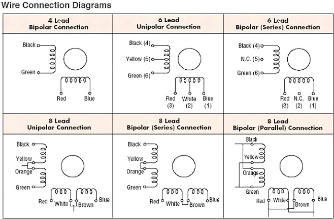 |
| Various ways in which motor wires can be connected |
Connecting a motor in series results in the inductance which is comparatively larger than a motor connected in parallel.
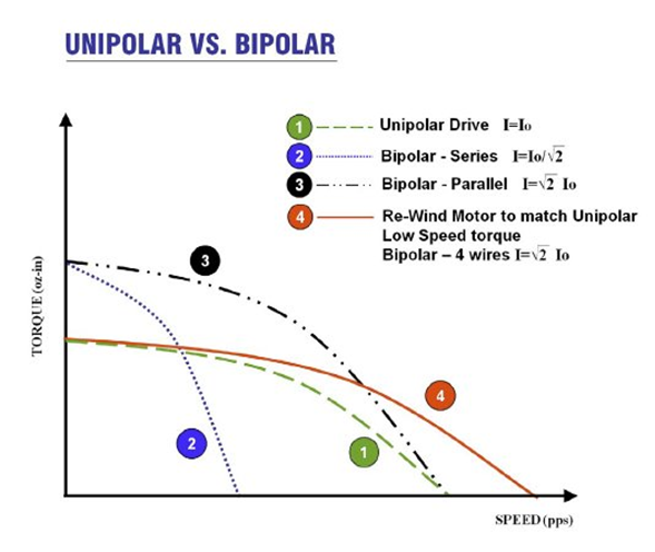 |
| Speed and torque variation of stepper motors wrt wiring configuration |
The result is that series connection will provide low speed performance and less motor heating, while parallel will provide high speed performance and an increase in motor heating. It's best to go with a four wire stepper motor since they are more universal and most drivers are meant for four wires. The encoder feedback may / may not be available separately depending on the kind of motor.
Servo motors have encoder feedback and there are separate wires for it which can be connected to the servo driver. Not all motor drivers have provision to take encoder feedback, so ensure that the driver is matched with motor. A new breed of hybrid step-servo are also there in the market which are basically stepper motors with encoder attached to it, and this may be fed to the driver which has provision to take position feedback. Yet another kind of hybrid step-servo motor may pack even a motor driver with encoder, so there may not be a need for separate driver for the motor. No matter the choice of motor you make, ensure that you keep in mind that motor and driver are matched if they are not an integrated unit since it can be prove to be a headache and can increase the task's complexity.


Motor drivers
When using a constant voltage drive, you need to be careful that you choose the supply voltage of the motor driver such that it is matched to the motor’s rated voltage and is kept constant. Constant voltage drives are simpler and less expensive than constant current drives. With a constant voltage drive, the resistance of the drive circuit i.e. motor winding limits the maximum current, while the motor’s inductance limits how quickly the current rises. A higher than required voltage will likely damage the motor and driver. In case of constant current drives, the supply voltage is adjusted to ensure that a fixed, constant level of current is provided to the motor.
Size
When we talk about size of stepper or servo motors, we are basically talking about the frame size of the motors. It's the part that will be used to mount the motor. The size are standardised to enable easy motor replacement. You may find motors of varying sizes from NEMA 8 to NEMA 48 and may be even higher.

NEMA is an abbreviation of the organization, National Electrical Manufacturers Association which governs the sizes and is responsible for standardisation. Before buying a motor, it's is still preferable to refer to manufacturer's specification since you may have other requirements like whether if there's a key, back shaft, and shaft length etc.
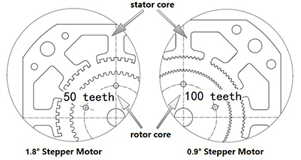
Step angle
As the name implies, stepper motor shaft rotates in discrete steps. Step angle is the smallest full step by which the stepper motor shaft can rotate. This angle is generally 1.8 or 0.9 degrees. So in case of a stepper motor with step angle of 1.8 degree, the shaft will complete one revolution i.e. 360 degree in 200 steps. Step angle can also be called as the resolution that the stepper motor.
Generally, step angle is not something to be worried about and even a stepper motor with a step angle of 1.8 degrees provides sufficient resolution.
Micro stepping
Micro stepping divides each full step into further discrete steps. Generally stepper / servo drivers provide several micro-stepping options. Step angle or full step is achieved when the current in both coils is equal. The microstepping is achieved by varying current level in the coils. Microstepping options that the drivers provide are generally - 1/2, 1/4, 1/16. 1/32 etc. Even with the use of 1/2 microstepping, you can double the resolution of the stepper motor. A thing to note however is that even if you choose the option of 1/32 microstepping with your stepper driver, it's not necessary that the motor will be able to achieve it. The advantage that microstepping offers in addition to increased resolution is that it helps reduce resonance, mechanical noise and makes the motion smooth. Generally, you may need to try out the microstepping options that work for you the best.
Increasing the microstepping, will increase the amount of pulses that the computer or controller board needs to send. Microstepping on all axis will further increase the amount of pulses that are sent through. So you should ensure that the board that you are using can handle such speeds. For example, a cheap chinese breakout board is rated for a speed of 1 Khz. In addition the holding torque decreases as you increase the microsteps.
Servos and steppers are controlled with the amount of current that flows through the windings. Larger voltages allow the motor to turn faster due to larger current flowing through the windings, since larger back EMFs can be overcome. And this allows the motor to run at higher mechanical powers since the speed and torque will be larger. So to control the current in the windings, we have two fundamental types of motor drives - constant voltage drives, which supply a fixed voltage to the motor, and constant current drives, which manipulate voltage applied to the motor windings, to ensure that a constant current is delivered to the motor.
V = IR
or
I = V/R
A stepper motor may just provide the resistance and current value in specifications and by using Ohm's law, we can find the voltage that you can safely apply. Using Ohm’s Law R x I = V (Resistance x Current = Voltage)
Example 1.4 Ohms x 2.8 Amps = 3.92 Volts
Example For 6mH per phase maximum voltage will be the following
1000 * SQRT(0.006) = 77 Volts
Matching servo and stepper drivers with the right motor is perhaps the most complex task and requires good know-how. If you are starting out, it's perhaps best to go with a kit if you are unsure whether if the driver is suitable for a motor or not.