What are constraints?
In one of the previous post, conditions of a valid sketch were provided. One of the condition of a valid sketch was mentioned, that it should be fully constrained (also known as Iso-constrained).
Constraints are in a sense, way of ensuring that our sketch does not change accidentally. Constraints also ensure that we know exactly how different lines, circles or other geometries exist within a sketch and how they are positioned. Constraints help us reduce the DOF of a sketch to Zero. These are basically of two types - Geometrical and Dimensional.
Geometrical constraints are applicable to the geometry of the elements for example, a line may be horizontal or vertical, a line may be tangent to a circle or may be parallel to another line. Or two circles may be maintaining symmetry about a line, or may be concentric etc. any constraint of such type is known a geometrical constraint.
Geometrical constraints alone are not sufficient in reducing the DOF to zero, so, in addition, dimensional constraints are used. These are basically dimensions, like length of a line, diameter of circle, distance between lines, distance from horizontal axis, distance from vertical axis etc. On the right, you can see one of the most simple sketch, and it is Iso-constrained. The degree of freedom of the sketch is zero because, the opposite lines of the rectangle have Horizontal / Vertical constraints indicated by H and V respectively. Also, the dimension of length and width are known which are 100mm and 70mm respectively. The distance from origin are known due the dimensions that are given which are 35mm and 50mm. Hence this makes the sketch Iso-constrained. Constraints are in a sense, way of ensuring that our sketch does not change accidentally. Constraints also ensure that we know exactly how different lines, circles or other geometries exist within a sketch and how they are positioned. Constraints help us reduce the DOF of a sketch to Zero. These are basically of two types - Geometrical and Dimensional.
Geometrical constraints are applicable to the geometry of the elements for example, a line may be horizontal or vertical, a line may be tangent to a circle or may be parallel to another line. Or two circles may be maintaining symmetry about a line, or may be concentric etc. any constraint of such type is known a geometrical constraint.
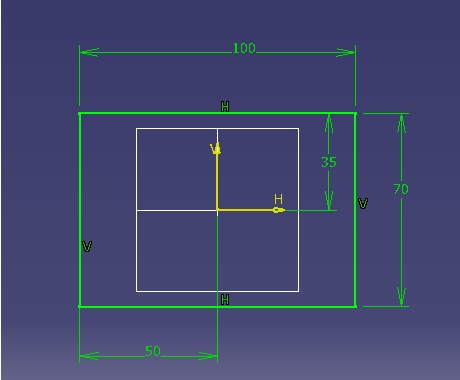 |
| A fully constrained sketch |
How do we apply constraints to a sketch?
Constraints defined in a dialogue box - This tool requires pre-selection of at least one element. Unless an element is selected, the option is not activated. The option can be used to apply constraints that involve only one element, like radius of circle, length of line, semi major axis of ellipse, horizontal or vertical orientation of line etc. The tool can also be used to apply constraints that involve two or more elements. For example, two or more elements together can be pre-selected and can be fixed together using Fix constraint. Tangency, which requires two elements can also be applied using this tool.
 |
| Constraints in a dialogue box |
Constraint - The constraint toolbar provides an easy way to apply dimensional constraints of all types. This is a more commonly used tool to apply dimensions. To be in continuous dimension creation mode, you can double click on the tool.
Contact constraint - The contact constraint is somewhat different option than tangency, tangency may be applied between any curve and a line or between a curve and a curve using constraint defined in dialogue box. The contact constraint can be applied between any two entities, however it is a smart tool. So, it would apply tangency constraints in the case where a curve element is involved as mentioned above, however in case of a line and line element, it would automatically apply the coincidence constraint. The tool can be used to apply tangency between two elements, coincidence between lines, points etc.
 |
| Tools present in Constraint toolbar |
Fix together - The
fix together constraint is used to fix relative position of several
elements with respect to each other. So, the elements would always be
fixed and would not move with respect to each other. This should not be
confused with Fix constraint present in Constraint defined in dialogue
box, where the elements are fixed with respect to the origin and cannot
move at all.
Auto constraint - Auto constraint can be used to apply automatic constraints to any number of elements, and dimensions can be created in stacked or chained manner. Such a tool is often counterproductive as creating dimensions requires more than a click, however it is easier if done manually since all it requires is to be familiar with elementary sixth standard geometry.
Animate constraints - Animate constraints can be used for preliminary analysis of mechanisms that can be represented with a 2D sketch. It may be used to analyze range of motion or to investigate a kind of variation any particular constraint may have. An exercise related to the tool is provided here. You can find discussion about practical application here. You can revisit this topic after you have mastered constraining of simple sketch exercises present ahead in this tutorial.
Edit multi-constraint - The tool can be used to edit existing constraint that are present in the sketch. The tool would display all existing constraints in a list when you select the tool. With the selection, you would also be able to see the constraint highlighted in the 2D space. For the purpose of visualization, any constraint that you modify will be shown as blue as long as you are in the Edit multi constraint command.