If you click on the black
dropdown button, you would be able to see all other options. The
toolbars can be dragged out and separated from the Profile toolbar.
Profile
Within
the profile toolbar there is a profile tool, which can be used to
create series of lines and arcs (tangent arc and three point arc)
continuously. Essentially, it has three options built in. Clicking on
the command selects the line option by default, however this can be
changed to make a three point arc or a tangent arc from the Sketch tools toolbar. (Trick: Clicking and Dragging the mouse while you are in Line mode can also start the tangent arc option.). To exit the profile command you would need to click on the profile button again or press Esc key.
 |
| Sketch tools options for Line |
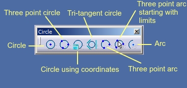
Circle toolbar can be used for creating circles and arcs. For creation, there are following options that you can use.
Circle
Circle
Using
this option you can make a circle using two points. One of the point is
the centre and other is the point through which the circle passes or
the radius value put in sketch tools. Both points can either be input
using Sketch tools toolbar or simply by a mouse click.
Circle using coordinates - This
option can be exercised if you know the centre point and the radius
value. Both values can be entered using Sketch tools toolbar or using a
mouse click.
Three point circle - If you know three passing points, you can create a circle using this option.
Tri-tangent circle - In this case you can specify three entities to which the circle may be tangent. These elements may be lines, circles or even other entities like parabola, ellipse etc. You can select these elements one by one using left click on the screen.
Three point arc - Using this option, you can create an that passes through three point. The three points can be selected such that the first point and last point are the end points of the arc while second point is the passing point.
Three point arc starting with limits - This is yet another option for creating an arc like the option above. However, in this case the first two points are the end points of the arc while third point is the passing point.
Arc - This is yet another option for creating an arc where you can make an arc by first specifying the centre point, subsequently radius or a start point, followed by the end point or by specifying the angle that the arc would make at the centre.
Spline
Smooth curves can be made on paper using free hand, or you can use a tool like french curves. However, to make such smooth curves in Catia, we rely on tools like Spline and Connect curve. The tools are present in the Spline toolbar.
Spline is a curve made by using a series of control points, through
which the curve passes. These points can be entered using mouse click or
using sketch tool toolbar. The spline can be ended using double click
or with Esc key. You can also edit the spline after making it, to do this, you would need to double click on the spline. The range of options are presented in the dialogue box that opens up.
In this dialogue box, there are options to specify points between already existing points, close the spline or specify the controls such as curvature or tangency at the selected points.
The spline can move freely if you move it using the control points and the curvature / tangency at each point is dynamic and keeps changing. However, after you apply curvature or tangency controls at the different points, they would not change when other points are manipulated. You can also edit the direction of tangency / curvatures and values after you have applied them, to do this, you would need to double click on the the direction arrows.
Connect curve - A connect curve can be between any two elements like lines, circles, splines etc. The curve can maintain point, curvature and tangency continuity and can be adjusted for tension and the direction in which these continuity is applied. These options can either be edited by double clicking or while the curve is being made using the Sketch tools toolbar.
The
conic toolbar offers tools for creating ellipse, parabola, hyperbola
and a conic (which is essentially a curve obtained by intersection of a
surface with a cone).
 |
| Conic toolbar |
 |
| Conic section |
Parabola by focus - Parabola can be made by providing the focus point, apex and start and end points of parabola. The points can be provides using mouse clicks or by entering using sketch tools toolbar.
Hyperbola by focus - Hyperbola can made by points using focus, centre, apex, start point and end point if you are using mouse, alternatively you can use Sketch tools toolbar to make a hyperbola.
Conic - A can be made using three options (found in Sketch tools toolbar) i.e. two points, four points and five points. Two points conic can be made by specifying start and end tangent which do not intersect or with an option where the start and end tangents intersect at a point. The four point conic can be made using the option where you just specify the four passing points and a conic will be made passing through these four points, or by specifying the start point and a tangent for this and similarly an end point and its tangent. A five point conic, requires you to input start and end points with three points in between, and these points are used to make a conic.
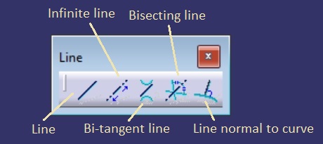
Line toolbar provides several tools, for making lines. You can either make a line with the use of two point as you do in Profile
tool, or you can make line using other elements. To these elements that
are chosen, the line may be made bisecting, tangent, perpendicular etc.
depending on the tool option you select.
Line - This
is the simplest way in which you can specify two endpoints using mouse
and make a line. If you use the Sketch tools toolbar you can also
exercise options of length as well as angle if you do not wish to enter
the second point.
 |
| Line toolbar |
Infinite line - Infinite line, as the name tells, can be used to make an infinite line. Sketch tool toolbar provides three options, horizontal line, vertical line and a line through two point. A line through two points can be used to make a line using two points or by providing a point and an angle at which this line should be made.
Bi-tangent line - A bi-tangent line is a line requires two existing elements to which the line can be made bi-tangent. So, a bi-tangent line can be made with the help of two circles, ellipse or a circle etc.
Bisecting line - This option can be used to make a line bisecting angle made between two non parallel line. The first line decides the sector where the bisecting line is made.
Line normal to curve -The option can be used to make a line normal to an existing curve or even a straight line. The line can extend in one direction or another option present in the sketch tools toolbar can be used to make the line extend symmetrically in both the directions.
Axis
Axis is made by specifying two points, the points can be provided using Sketch tools toolbar or using a mouse. The axis is important from the perspective that it gets automatically recognized in Part design workbench when you select Shaft or Groove command (will be discussed ahead in part design) and can be used to make cylindrical parts or parts that have a similar section across axis plane.
Parts like bucket, flower pot, piston may employ an axis in a sketch to make majority of the features of the design. We will work with the command when we get to the part design workbench and see how it works.
 |
| Axis tool |
There are many ways in which you can make points on a sketch plane. Tools available in Point toolbar are explained below.
 |
| Point toolbar |
Point by clicking -
The option can be exercised if you wish to create point by a mouse
click. In the sketch tools, you also have an option of entering
Horizontal and Vertical coordinates.
Point by using coordinates - The option opens a dialogue box and besides an option of creating a point using Horizontal and Vertical distances for creating a point i.e. Cartesian coordinates, you also get an option to create a point with Polar coordinates, where you can provide an angle and distance from origin.
Equidistant points - The option can be used to create number of equidistant points on a straight line, arc, circle, ellipse etc.
Intersection point - The option can be used to create a set of points where two elements (circle with line, circle with circle, line with line etc.) intersect.
Projection point - Projection point can be used create points with the help of existing points, which are used to drop normal on curve or line, the project point is essentially a point where the normal line intersects the curve. In a single instance you can select any number of points which need to be projected on a curve, line etc. and create multiple points along with perpendicular construction lines.


