To create a bottom-up assembly, you would require already modeled parts saved in a folder. If you have not made the parts or do not wish to make them, you can download the parts using
this link. These parts have been made using Catia V5R21, so you can use the same release or higher to work with these parts.
 |
| Assembly file, Product1 created |
The first step after downloading the parts is to create a new file i.e. an assembly file, because an assembly will be created by using this file. You can either use the file that opens up by default when you open up Catia, since that is an assembly file with .CATProduct extension. Or you can create a new file using the shortcut
Ctrl + N and choosing the
Product option. As a first step, you should save this file in the same location where the part files are present. In this case, you can see, we have not changed the default name and the file name is Product1.
 |
| Moving the cursor over workbench tool will display the name of current workbench |
As a next step, you should confirm that you are in the assembly design workbench. When you hover the cursor over the workbench toolbar, it will show the name of the workbench you are in at the moment. If you are not in the assembly design workbench, you should navigate to it using the path Start > Mechanical > Assembly design.
To work on the assembly, we would need to call parts one by one, and apply constraints. So, you can follow the steps below to create an assembly.
- Use the tool 'Existing component' in the Product structure tools, and select the Product in specification tree, subsequently select the dialogue box to select Part3.
- Apply 'Fix component' constraint to the Part3. This will arrest all degrees of freedom of this base part. The constraint you apply will be visible in the specification tree. To update all constraints use the command Ctrl + U everytime you apply a constraint.
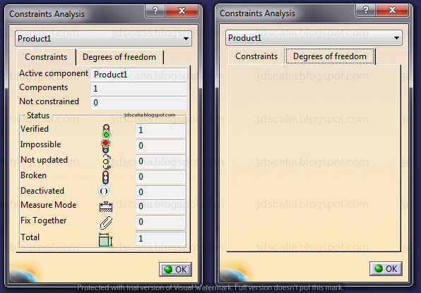
To check degrees of freedom, we follow the path Analyse > Constraints. The tab Degrees of Freedom, will let us know if there are any parts that are free to move.
 |
| Analyze > Constraints |
Since, we do not see any parts in this tab, this tells us that all degrees of freedom of all parts are arrested and we don't need to apply more constraints. And the Constraints tab will provide information about all constraints that are applied and the status of constraints. After calling first part, we would call more parts in the workbench.
 |
| Apply coincidence constraint between base part and shaft as shown |
- Use 'Existing component with positioning' and select the Product in the specification tree to insert Part2.
- To originate the part properly, use Smart move or Manipulate tool. Subsequently, apply coincidence constraint between the axis of the base part and the shaft as shown. This will align the two parts and arrest some of the degree of freedoms of the shaft. You can check the DOF (Degree of freedom) using the same path Analyze > Constraints. To further analyze DOF, double click on the component shown in the analysis list. This will show the different DOFs. We can see that, the shaft can translate about axis and rotate about axis.
 |
| Translation and Rotation about axis still present |
- To first arrest translation, we will apply Offset constraint between the faces that are shown and give an offset value of 20mm. If needed, this offset value can be adjusted as needed. This will align the faces of the back of shaft with that of the base. To update the constraints, use Ctrl+U.
 |
| Apply offset constraint with value of 0mm |
After this, only rotation of the shaft shall remain, which we need to arrest.
- To arrest rotation, apply an angle constraint between, plane of the shaft and face of the base part as shown. Apply any angle value, since it does not affect us. If the plane is not visible, you will need to unhide it from the specification tree of the respective part.
 |
| Applying angle constraint between planes |
- Use same process and call Part5 in the assembly
- Apply coincidence constraint between the cylindrical part and remaining hole.
- Apply offset constraint between the back of base part and cylindrical part. Also apply angle constraint between planes as we applied previously.
 |
| Constraints applied to three parts in total |
- Insert Part4 using same process. The part is a key which goes between shaft and cam. This time, we will apply two constant constraint between the faces of shaft and key as shown on left and right.
 |
| Apply two contact constraints |
- Now the key have only one DOG remaining, we will arrest it by applying coincidence constraint between one of the shaft edge and key edge as shown.
 |
| Coincidence constraint applied between Key and Shaft |
- Now, the last step is to call the last part i.e. Part1, which is a cam. And constrain it using same constraints we have used to far. We will first apply the coincidence constraint. Followed by offset between plane of cam and shaft as shown.
 |
| Coincidence and Offset constraint applied |
You can now analyse the constraints and see the remaining degree of freedom. The remaining degree of freedom is only rotation.
 |
| Remaining DOF and arresting it with contact constraint |
Which you can arrest by applying contact between planes of cam and key as shown.