Making a top-down assembly is same as making a bottom-up assembly, to the extent that you would need to apply the constraints in the same way as you applied during the bottom-up assembly. However, in case of the top-down assembly it is required that we start with an assembly file and make all parts from within that particular assembly file, unlike in case of bottom-up assembly, where we called already modeled parts and assembled them.
For the top-down assembly, we would create a three part assembly. By creating this assembly in the top-down manner, we would learn how to effectively navigate between product / part environments and modify parts and assemblies from within the single document. The drawings for these parts are present below. We have kept the parts simple for the sake that you can practise easily.
 |
| Top-down assembly - Assembly and Parts drawing |
When you open Catia, by default, the assembly file opens up. As a first step, save this file using Ctrl+S in a desired folder and give it a name of your preference.
 |
| Saving assembly file in folder |
Subsequently, we move to creating more part / assembly files. We would first create Part1. To create this, we would use the tool Part present in the Product structure tools toolbar and select Product1 in the specification tree. You would notice that it would add Part1 under the Product1 assembly.
 |
| Part1 added |
 |
| When saving after creating Part1 in assembly, the prompt will be shown |
Now the files are saved. To create Part1, you would need Part Design workbench. So, to edit / create Part1, you would need to double click on Part1 file in the specification tree as shown. Alternatively, you can use right click to open part in new window and edit the part there. The Product1 will show all changes automatically. You can return to the assembly design workbench by double clicking on Product1 in the specification tree. I assume that you shall be able to create the Part1 on your own. If you don't know how to use Part design workbench, you can find all topics here.
To create Part2, we will again use the same tool i.e. Part. Note that if we were to create a sub-assembly, we would have used the Product tool in the Product structure tools. Now, when you try to create Part2, you will be shown another prompt, "Do you want to define a new origin for the new part..". This dialogue box will actually be shown every time you create a new part.
 |
| Option provided when you create a new Part in assembly |
If you choose Yes, you will be able to define new origin point by clicking and the planes or the part will be created on that point instead of default origin. Likewise the prompt will be repeated when you try to save the file. You can design the part in the same window by double clicking or using the open in new window option. Parts can be assembled in the same way as you did in case of the bottom-up assembly. If you did not read about bottom-up assembly, you can do so here.
Copy and Paste
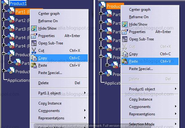
What if a part is being used several times in an assembly. You can either call it into the assembly by using the tool, Existing component or Existing component with positioning, or you can simply copy and paste the part within the specification tree if you already have one instance.
 |
| Copy and Paste parts / sub-assemblies |
To do this, simply right click > copy the Part instance in Product tree and choose right click > paste. Keep in mind the Product where you paste the file, since you can even paste the part in a sub-assembly. In the same way, you can paste sub-assemblies too into another assemblies.
How to use assembly features in Catia?
Assembly features are a great way for designing parts / assemblies. Creating assembly features requires at least two components. You can create assembly features only between the child components of the active product. There are features that most of time are applied in the final stages i.e. when the parts are in position and their relative positions would not change since changing constraints or positions may also change the assembly features applied. The features that you can create in assembly are Split, Hole, Pocket, Remove, Add. Let us see, how each one may be applied.
Split
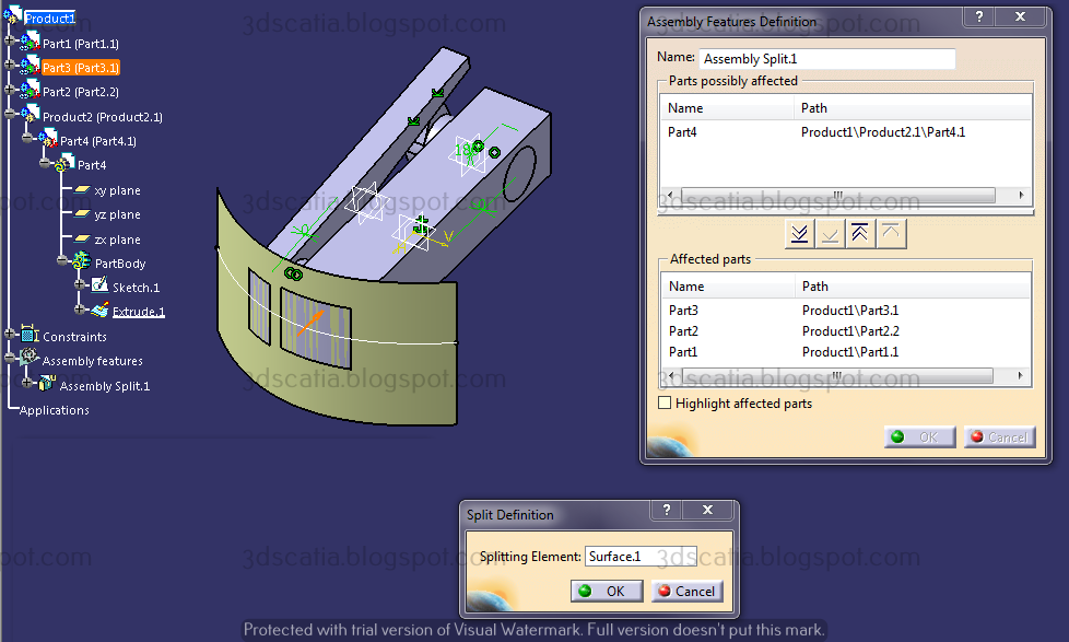
As we know, a plane or a surface can be used for split. The surface may belong to any part, you can still use it to perform the split on any part in the assembly document as long as you perform it by activating the main assembly (by double clicking). Below you can see the split being performed using a surface on two of the parts using Product1 as active document.
 |
| Performing assembly split |
Whenever you perform the assembly operations, an assembly features definition dialogue box opens up. Above part shows the parts list on which the split can be performed, below are the parts on which the split will be performed. You can move parts to below part using arrows if you wish to include them and perform a split.
Hole
In much the same way, you can use the hole assembly feature. The hole that is created as an assembly feature will be shown under assembly features in the specification tree.
 |
| Making assembly hole, see the specification tree where the positioning sketch is located |
A thing to keep in mind is that you cannot position the hole while making the assembly feature. However, the first part you select for hole i.e. from where the hole starts will have the positioning sketch which you can edit for positioning hole correctly. The parts in which you wish to make holes, you can move those to the bottom section using arrows.
Pocket
Pocket assembly feature is dependent on the sketch that you may have made in any of the part file. You can use that sketch to create a pocket assembly feature. It's very much like we utilised a surface of a part for split.
 |
| Assembly pocket (elongated hole) made using a sketch in Part2 |
The sketch that you use can be made specially for the feature or re-use an already existing sketch. Everything else works exactly in the same manner.
Remove
We used boolean operation between bodies and saw how it worked, if you have forgotten, you can read it here. The operation is just like that, however the only difference is that in this case the operation is applied between different Part files.
 |
| Blue part removed from Orange using Assembly operation - Remove |
Where you may use this, is upto your imagination. One place where this may readily work is, say you have designed a part and wish to make mould half cavity. So this can be used for creating of the half quite easily without the use of advanced mould design workbench.
Add
Add can be used in exactly the same way as remove. You may use it where you may think that two parts can be combined. You may use this to create the other half of the mould.