The
user selection filter toolbar can be divided into two sections. On the
right, it has filter modes and on the left it has different filter types
(as seen in picture), such as point filter, curve filter, surface
filter and volume filter. In the filter mode section, it has filter
modes - Geometrical element filter and Feature element filter. Let us
see what are these.
Filter type - The
filter type essentially let you select only that particular element for
which you have selected the filter for. For example, when point filter
is selected, the cursor will only be able to select points in the
sketcher or in the part workbench. You can also choose multiple filter
types at once to extend your selection. For example, if you wish to
select all points and lines, you may select the point and curve filter
for that.
The sketch can look intimidating at first considering it has a complex profile and lot of arcs. However, on close inspection you will find that almost every dimension is given and position is well defined about vertical axis.
Exercise
Perhaps the best way to make this sketch would be to start by keeping in mind the parts that are symmetrical and see if you can keep it symmetrical about vertical or horizontal line. In this case, the upper part looks symmetrical vertically, so we will proceed accordingly.
Position of circles and some lines is very well defined, so they can be made first, followed by geometry that's dependent on these with constraints like tangency etc. And finally, we can trim the excess parts and apply / modify constraints as needed. You can watch the video below for reference.
This exercise is fairly complex for a beginner, and would give the mind some exercise. It would help you know, as to how different tools from operation toolbar, selection filter, constraints and profile toolbar are used together.
If you see and analyze the diagram on the right, you would be able to see that in majority it is actually composed of circles or parts of circles which are offset from each other vertically or horizontally by some distances. So, it may be best to start with that and then proceed onto making other elements of the sketch around it.
Exercise
First we can create series of multiple circles with the help of circle tool. The distances of the center points are well known from the left most point of the sketch, so we can use that as origin to reference the centers of our circles.
Also, we know well the position of various lines, so that can be made easily too. Besides, we also know the arcs radius and other entities to which they are tangent. The exercise has been covered in two videos below (showing different methods), you can watch them below.
The exercise displayed requires creation of the outline, which can be made using profile tool or line tool. While center hexagon can be made using predefined profiles.
Exercise
We may first start with a rough outline first, which would resemble the sketch. Subsequently, we would be using tools from the constraints toolbar and apply the constraints keeping in mind the geometry and dimension of the sketch. While making the sketch we would be aiming for simplicity. We would try to make it in a way such that modification is easy, and it's easily understood by anyone else.
The exercise would require use of line, circle and corner tools.
While making this exercise, we would be aiming for objectives like that
it should be simply constrained and should be made such that it's easy
to understand by others.
Exercise
In addition, we should also try to constraint the sketch similar to the way in which it has been dimensioned in the diagram. You can follow the video below to see how we would exactly make this sketch.
In one of the previous post, conditions of a valid sketch were provided. One of the condition of a valid sketch was mentioned, that it should be fully constrained (also known as Iso-constrained).
Constraints are in a sense, way of ensuring that our sketch does not change accidentally. Constraints also ensure that we know exactly how different lines, circles or other geometries exist within a sketch and how they are positioned. Constraints help us reduce the DOF of a sketch to Zero. These are basically of two types - Geometrical and Dimensional.
Geometrical constraints are applicable to the geometry of the elements for example, a line may be horizontal or vertical, a line may be tangent to a circle or may be parallel to another line. Or two circles may be maintaining symmetry about a line, or may be concentric etc. any constraint of such type is known a geometrical constraint.
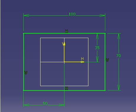
A fully constrained sketch
Geometrical constraints alone are not sufficient in reducing the DOF to zero, so, in addition, dimensional constraints are used. These are basically dimensions, like length of a line, diameter of circle, distance between lines, distance from horizontal axis, distance from vertical axis etc. On the right, you can see one of the most simple sketch, and it is Iso-constrained. The degree of freedom of the sketch is zero because, the opposite lines of the rectangle have Horizontal / Vertical constraints indicated by H and V respectively. Also, the dimension of length and width are known which are 100mm and 70mm respectively. The distance from origin are known due the dimensions that are given which are 35mm and 50mm. Hence this makes the sketch Iso-constrained.
The operation toolbar comprises of tools that can help extract elements from 3D geometry for the purpose of sketch creation or help modify the sketch by helping elements rotation, re-limitation or modification.
Operation toolbar
The tools and toolbars present in the operation toolbar are corner, chamfer, relimitations toolbar, transformation toolbar and 3D geometry toolbar.
The
Profile toolbar can be used to create lines, circles, arcs, keyhole
profile, rectangles, ellipse, hexagon etc. All buttons in the image will
show options such as rectangle, circle, spline, ellipse, line etc. when
you hover the cursor over them, however each button with a black colour
dropdown button is a toolbar in itself.
Profile toolbar
If you click on the black
dropdown button, you would be able to see all other options. The
toolbars can be dragged out and separated from the Profile toolbar.
Sketcher
is the basic workbench, and it is used to create a 2D sketch. The sketch forms the basis of a 3D model. A sketch can be created on a
2-Dimensional plane such as XY, YZ, ZX or any other planar surface of
existing part which is two-dimensional. It can be created using various tools present in the
Profile toolbar, and modified using tools in Operation toolbar and
Transformation toolbar. However, before we start to make sketch and learn about the tools that are available for sketching, there are some conditions you should remember.
a) The sketch should not be self-intersecting b) The sketch should not be open c) The sketch should be Iso-constrained (i.e. it should have no Degree Of Freedom) d) There should be no standard points (i.e. all points should be construction elements only)
a) The first method is that you double click on the icon present on the desktop. This is perhaps the way you start all other programs too in Windows.
b) Second method which pertains to windows only is that you open the task manager by using the ctrl+alt+delete buttons simultaneously and start the process “cnext.exe”.
Using command to start Catia
c) Third method is that you issue the "cnext.exe" command from the start menu using run. The third method also pertains to windows only. All three methods are essentially the same since each is starting the cnext.exe process in the background.
What is GUI (Graphical User Interface)?
GUI refers to the Graphical user interface of the software. The interface is essentially a collection of windows, tools and working area which helps the user interact with the software. User is able to select different tools, apply commands, manipulate the model with the help of GUI. It comprises of menu bar, work area, specification tree, prompt zone, toolbars etc.
Application window - The GUI of the software consists of the application window, which is essentially the window screen within which the software operates. So basically it is the overall envelope on the screen that is occupied by the software.
Menu bar - Menu bar is also known as the main menu which is present on the top. It has the options "File", "Edit", "View" etc. all options that you generally see in other windows applications.
Toolbars - Every workbench has appropriate tools, suited for the needs of that workbench, these are organised under different toolbars. You can double click on them to send them back inside or bring them out. You can also drag them inside / outside along with using mouse left click. In case a toolbar is missing, you can bring it back from the main menu or right click on any of the toolbar and see the list of visible toolbars at any moment.
Graphical user interface
Work area - Work area comprises of specification tree on the left, planes xy, yz and zx at the centre, compass at the top right and whatever geometric model or assembly that you create.
Specification tree - Present on the top left, you would find XY, YZ and ZX plane along with it, it documents all the features, sketches, planes, surfaces and geometries that you create in a part document, it will also let you know the relationship between the features. We will discuss this in more detail in future videos.
3D Compass - The 3D compass can be seen on the top right corner can it can be used to rotate as well as move parts. You simply need to use the left click to do this. This is an alternative way to move part if you are not comfortable using the mouse for navigation. The red dot on the top can be used to freely rotate the part with respect to mouse movements. All you need to do is left click and move the mouse. The 3d compass has some other advanced features too that we will discuss in future videos.
Prompt zone - The prompt zone is present on the bottom left area and this displays appropriate prompt pertaining to the command that you select. For example, if you press the Sketch button from the Sketcher toolbar, it would display the next logical thing to do i.e. to select a plane or planar surface on which you wish to make a sketch. This is handy and provides useful clues for people who are just starting to learn Catia.
Power input mode - Power input mode can be used to invoke commands that you may normally do using toolbars, for example I can enter c:pad command to open pad dialog box likewise c:sketch may be used to draw a sketch. I have seldom used it, but there are oddballs you know, so, I have mentioned it for their sake.
File types
There are many proprietary file types of Catia. These are:
.CATPart,
.CATProduct,
.CATProcess,
.CATMaterial,
.CATAnalysis
.CATDrawing etc.
A file type is associated with the workbench in which it is created. For example, whenever you create a file in any of the workbenches such as Sketcher, Part workbench, Generative Sheet-metal design, Wire-frame and Surface design, Generative surface design etc., it will have the .CATPart extension. Also, with the .CATPart file that you create, you are free to navigate in all the workbenches that are mentioned above and can use any tool present in these workbenches to work on your model. However, suppose, if you need to assemble parts to make a product or sub-assembly, you would need to work with an assembly workbench, and it would require a .CATProduct file. Which is the extension of all file generated in Assembly Design workbench. Likewise files created in drafting workbench of Catia have a .CATDrawing extension.
Likewise .CATAnalysis is the file extension of analysis done on parts to find stress and other value. .CATMaterial is the extension of various materials such as Iron, copper etc. or any material that you create yourself by specifying Young's modulus etc.
Compatibility
The file types are nothing to be worried about, as these are created automatically by Catia. A thing to keep in mind is the version of Catia in which you are working since compatibility issues can arise if you try to open files created in one version of the software with another version.
Catia
does not support backward compatibility i.e. a file saved/opened in
V5R19 can be opened in R 19, R20 or higher version. However, you would
not be able to open the file in any previous version like R18, R17 etc.
You
can downgrade a file and open in previous Catia versions down to R6,
however, specification tree would be lost and it would be solid without
any history. Alternatively, you can save the file as STEP which would
give the same result as downgrading. Saving the file as STEP is more
straightforward than downgrading.
Catia Workbench navigation
Catia offers different workbenches, which are essentially environments where tools required for a specific task are present. And we can navigate through them using the "Start" button, present on the top left. Each workbench serves a specific purpose and has tools suited for that kind of work. For example, Drafting workbench will offer tools related to drafting, assembly design will let you assemble parts, Sketcher workbench will let you sketch, which can subsequently be used to create a part in part design workbench, so on and so forth.
Catia does not support UNIX for client end anymore and only windows version is available for the latest releases of the application. So, basically it's a windows application that can be installed in a straight forward manner at least on the latest version of windows.
Catia installation - Progress bar
Installing Catia on Windows
You would need to run setup files which are executable (.exe) files. Depending on the version of Catia, it may have either one, two or even three setup files contained in separate folders / CD ROMs. These need to be installed in the correct sequence.
Dassault Systems, or any reseller that you may contact, is likely to recommend you the best and the latest machine for running Catia. Which is likely to have suitable graphics card a processor suited for the job. Working on large assemblies requires high-computation resources, so they are right in pointing out that you should use the latest and the best machine for working with Catia.
Catia is an acronym for - Computer-aided three dimensional interactive application. It was formerly known as CATI (Conception assistée tridimensionnelle interactive – French for interactive aided three-dimensional design) and began as an in-house project by Dassault Aviation in France for the development of Mirage fighter jet. The software was found to be quite useful and was hence marketed and commercialised by Dassault through its own subsidiary. IBM joined later (in 1981) to become a non-exclusive seller of the software. It is a software that not only enables the user to model rich and complex designs, the software can also be used for validation and for running simulation of all sorts. The software finds application in mechanical industries and is also used widely in other fields like electrical, automotive, aeronautical engineering. Infact, it's considered an industry standard when it comes to surfacing. While there are many other softwares like Solidworks, NX etc. and they are widely used too, no software comes close to Catia when it comes to creating surfaces which can be directly utilised for creating tooling or end product generation. It's an application that even helps with manufacturing and can be used for creating CNC code for tool path movement. So basically, it offers an end-to-end solution for product creation. It has three platforms (P1, P2 & P3) on offer and is a scalable solution that's suited for all sorts of industries. I am working with Catia V5 R21 at the moment. V5 refers to the version of Catia, and R21, refers to the minor release.